Unmanned Aerial System
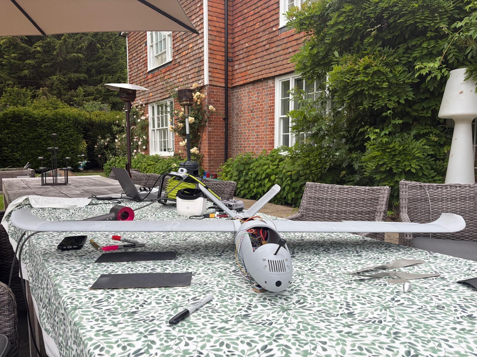
Designed, built and tested a fully 3D printed UAS from scratch. The aircraft is a 1.4m wingspan, V-tail pusher configuration. AUW has been reduced from 2.5kg to 1.8kg across design iterations through reduction of printed wall thickness from 2 perimeters to 1. Constructed with 50 custom designed 3D printed parts, the goal was to create an airframe that could be rapidly reproduced and repaired using a simple desktop 3D printer, making it suitable for deployment in resource-limited environments.
Project Details
Technologies
XFLR5, Fusion 360, 3D Printing, ArduPilot
Category
Aerospace Engineering
Status
v3 Redesign in Progress — 2 flight tests completed
Institution
Independent Project
Key Features
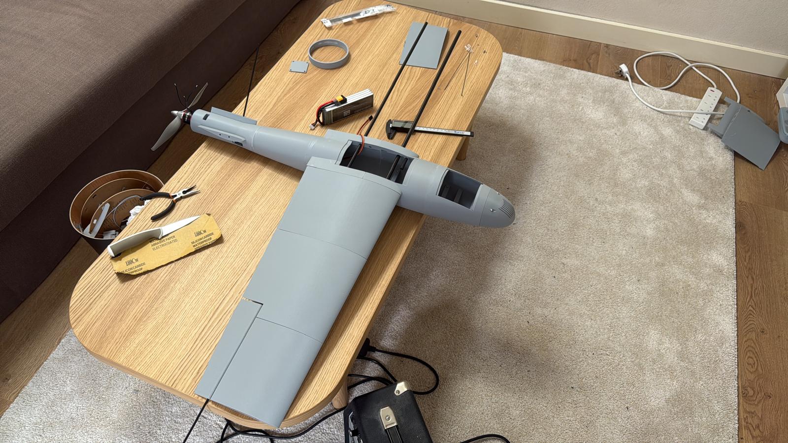
- Material: pre-foamed LW-PLA + carbon fiber wing and tail spars
- 5000mAh 4S LiPo battery for ~45 minutes flight time
- SpeedyBee F405 Wing flight controller with ArduPilot firmware
- On board FPV camera with 5.8GHz video transmitter for real-time telemetry and video feed
Project Overview
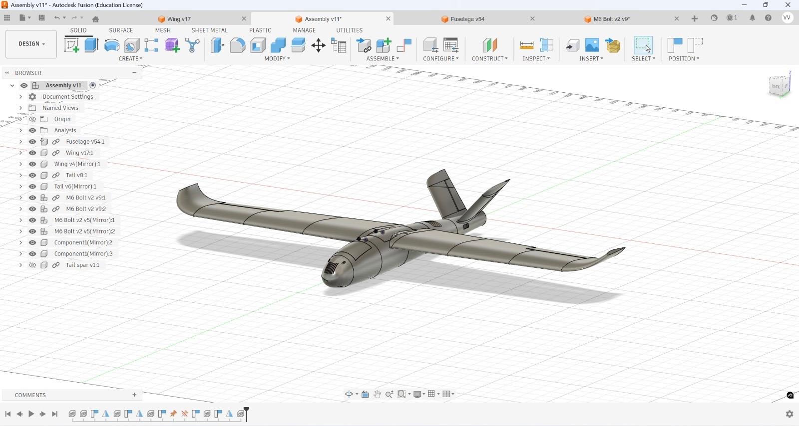
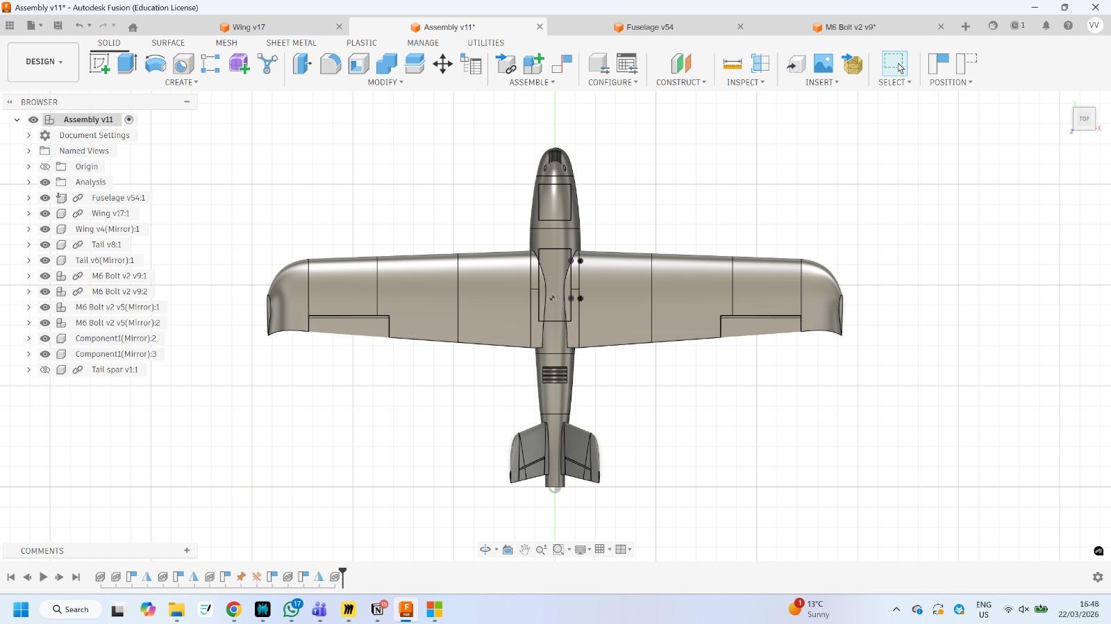
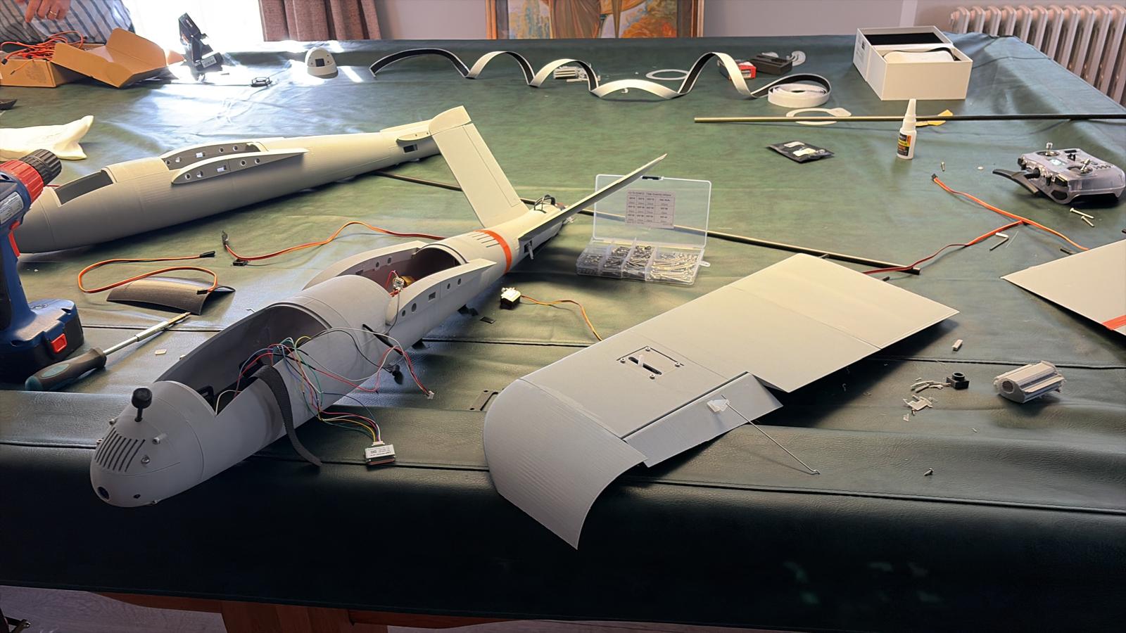
The UAV project began as a solo effort to design, build, and flight‑test a fully 3D‑printed unmanned aerial system from the ground up. The V‑tail pusher configuration was selected to balance aerodynamic efficiency, structural simplicity, and ease of manufacturing, while supporting manual and semi‑autonomous operation.
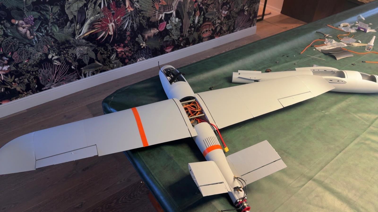
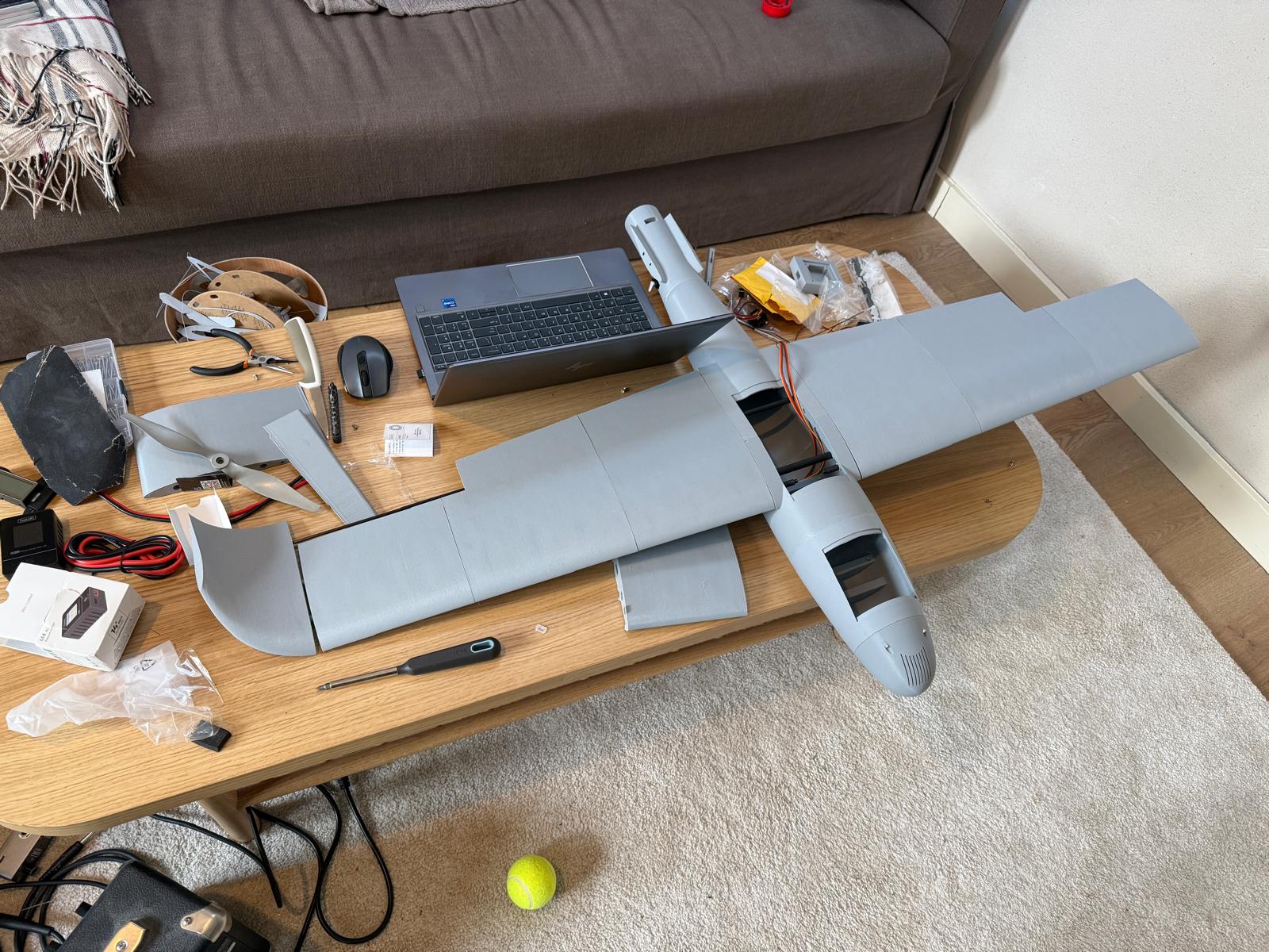
The airframe was constructed entirely from 50 custom 3D‑printed parts, optimized for additive manufacturing constraints and rapid assembly. Each component was designed to snap or bolt together, enabling quick repairs and straightforward replacement of damaged sections in the field.
Integration of the flight controller, receiver, and telemetry electronics formed a core phase of the project. The system was laid out to minimize wiring length, reduce interference, and keep the center of gravity within the required envelope, while allowing for future upgrades and sensor additions.
Technical Implementation
The flight control system utilizes a SpeedyBee F405 Wing APP board running ArduPilot firmware. Sensor fusion algorithms combine data from the IMU, GPS and barometer to maintain stable flight in various weather conditions.
Ground station displays real-time telemetry data, including altitude, airspeed, battery voltage, GPS coordinates and more on a laptop screen. The same data is also overlayed on the pilot's FPV video feed, providing critical situational awareness during flight operations.
The flight controller supports GPS-assisted stabilisation and return-to-home functionality. Full autonomous waypoint navigation is planned for a future test campaign following completion of stabilised flight validation.
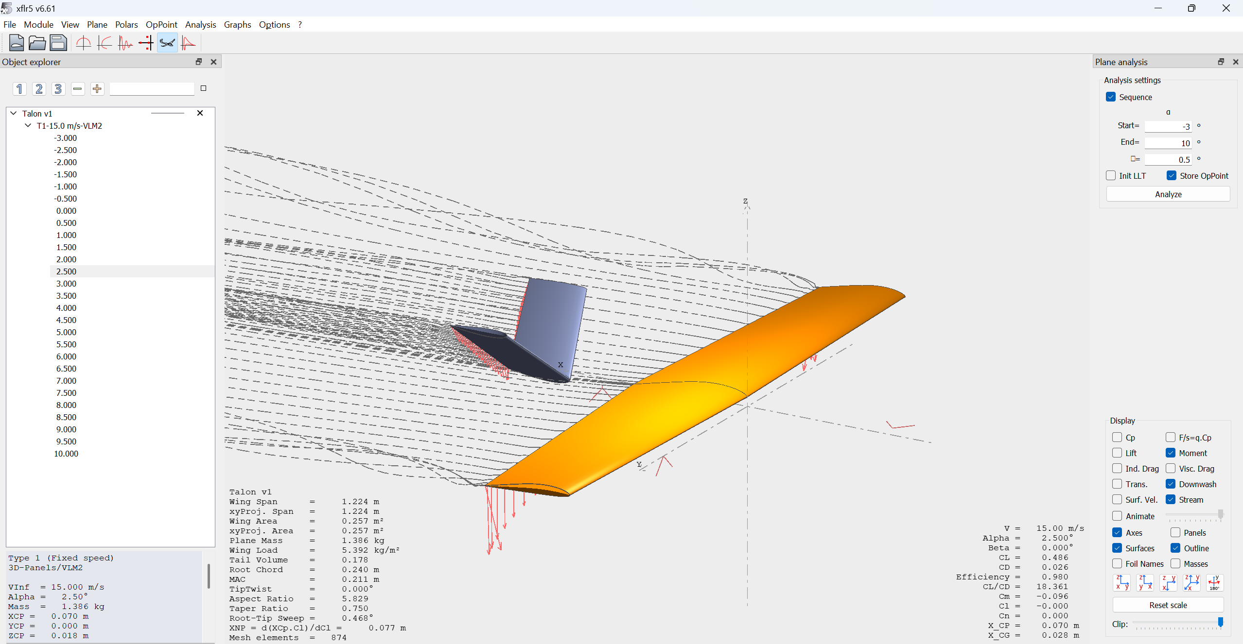
Stability Analysis (XFLR5 — v3 Airframe)
Analysis type: Type 7 Stability Analysis, VLM2 (lifting surfaces only). Condition: level flight at α = 0.10°, V = 17.43 m/s. Model mass: 1.386 kg (primary structural components and battery; excludes flight controller, FPV system, and minor hardware). Full AUW is approximately 1.8 kg.
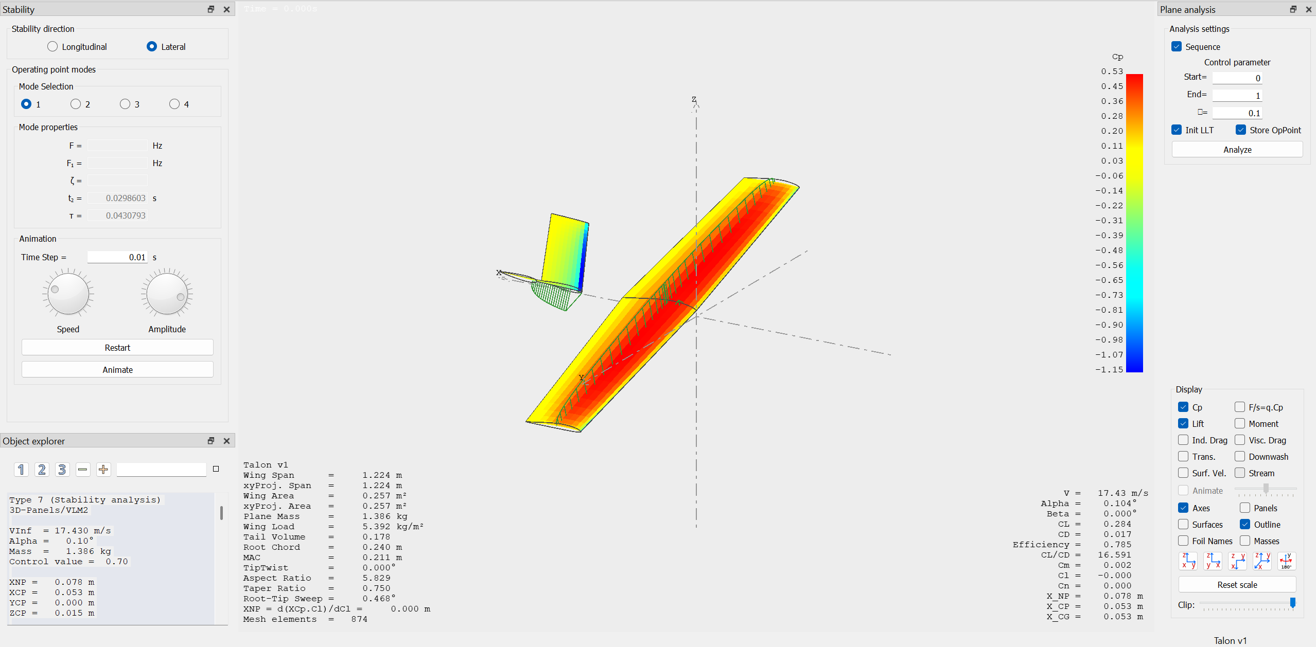
Static Stability
The neutral point (NP) is located at 0.078 m and the centre of pressure (CP) at 0.053 m aft of the reference point, giving a static margin of 11.8% MAC (MAC = 0.211 m). This confirms the aircraft is statically stable in pitch — the NP lies ahead of the CP, meaning any pitch disturbance generates a restoring moment. An 11.8% margin sits comfortably within the 5–15% range typically targeted for stable fixed-wing UAVs.
This is supported by the pitch stability derivative Cmα = -0.531, which is negative as required — indicating the aircraft generates a nose-down pitching moment with increasing angle of attack. Directional stability is confirmed by Cnβ = +0.042 and roll stability by Clβ = -0.015, a small dihedral effect consistent with a flat-wing design.
Longitudinal Dynamic Modes
Short period mode — Eigenvalue: −6.139 ± 8.412i | Frequency: 1.658 Hz | Damping ratio: 0.590. The short period mode is well-damped and will be largely imperceptible to the pilot in practice.
Phugoid mode — Eigenvalue: −0.006 ± 0.690i | Frequency: 0.110 Hz | Damping ratio: 0.008. The phugoid is lightly damped but stable, with a slow cycle that is easily corrected by the pilot or flight controller.
Lateral Dynamic Modes
Roll mode — Eigenvalue: −23.213 | Time constant: 0.043 s. This indicates responsive, predictable roll behaviour.
Dutch roll mode — Eigenvalue: −0.494 ± 5.139i | Frequency: 0.822 Hz | Damping ratio: 0.096. Stable and convergent, with further suppression expected from ArduPlane's yaw damper.
Spiral mode — Eigenvalue: +0.096 | Time to double: 7.2 s. The mild instability is manageable by both pilot and flight controller in stabilised mode.
Summary
All critical stability requirements are met. The aircraft is statically stable in pitch, roll and yaw. The short period mode is well-damped and the phugoid is stable with low frequency. Laterally, the roll and Dutch roll modes are stable; the spiral mode shows mild instability consistent with a flat-wing configuration, manageable by both pilot and flight controller. The analysis was conducted on a surfaces-only VLM2 model, so fuselage aerodynamic contributions remain a known limitation.
Flight Testing Results
Flight Test 1
The initial flight test resulted in the loss of the aircraft. Root cause analysis identified two contributing factors: the thrust vector from the motor acting below the centre of gravity, creating a pitch-up moment; and the cambered V-tail aerofoil generating downward lift, compounding the pitch-up tendency. The aircraft was recovered for redesign.
Design Fixes (v2)

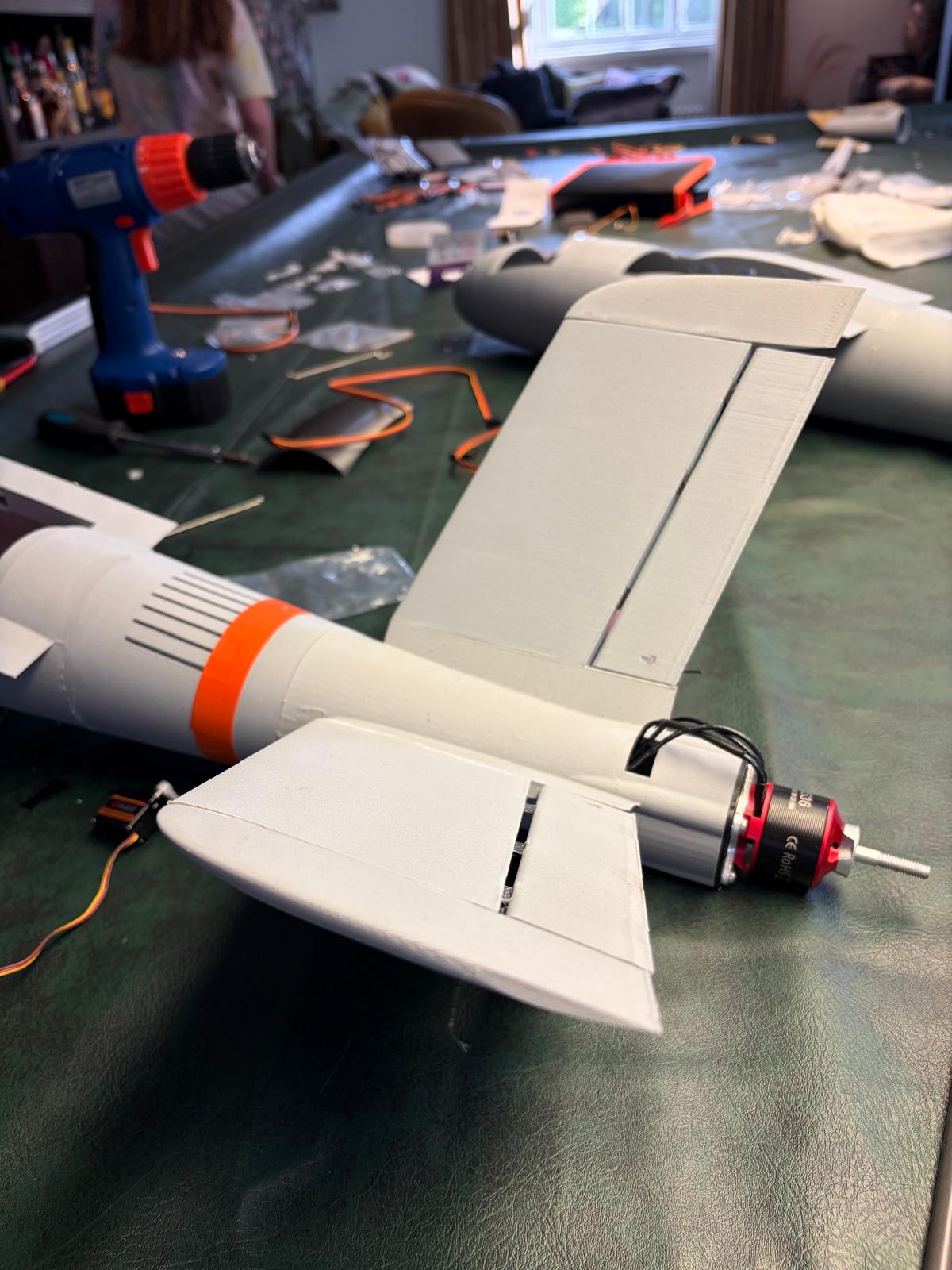
- Motor mount tilted about 1.5 degrees to align the thrust vector directly through the centre of gravity
- V-tail airfoil changed from cambered to symmetrical section to eliminate reduce overall downforce and improve handling consistency in yaw
Flight Test 2
The second flight test confirmed the aerodynamic fixes — the aircraft flew wings-level immediately after launch, validating both design changes. The flight ended in a crash attributed to insufficient launch speed and throttle input rather than any airframe issue. This was a launch procedure failure, not a design failure.

Current Status
v3 redesign is in progress, targeting improved launch procedure, onboard data logging via SD card, and multi-angle camera coverage for post-flight analysis.
Lessons Learned
The two flight test campaigns reinforced the importance of systematic root cause analysis over iterative trial and error. The v1 pitch-up failure was initially attributed to pilot error, but closer analysis revealed two independent aerodynamic causes — both of which were resolved in v2. The v2 wings-level flight confirmed this diagnosis. Future test campaigns will include onboard data logging and multi-angle video to reduce reliance on visual observation for post-flight analysis.